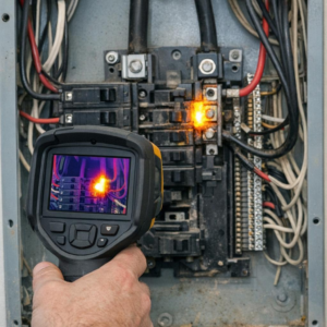
What if your “machine fault” is really just bad data? In industrial condition monitoring, signal noise can turn healthy equipment into a false alarm-or hide the early warning signs of real failure.
Vibration sensors, accelerometers, current probes, temperature transmitters, and ultrasonic devices all depend on clean signals to detect bearing wear, imbalance, looseness, cavitation, and electrical faults before downtime occurs.
But in real plants, noise comes from many places: poor grounding, EMI, loose cabling, incorrect sensor mounting, aliasing, low-quality power, and harsh mechanical environments.
This guide explains how to identify the source of sensor noise, separate it from legitimate machine behavior, and apply practical fixes that improve data quality without compromising fault detection.
What Causes Signal Noise in Industrial Condition Monitoring Sensors?
Signal noise usually comes from the environment around the sensor, not the sensor alone. In industrial condition monitoring, accelerometers, temperature sensors, pressure transducers, and current sensors often sit near motors, variable frequency drives, welding equipment, relays, and high-voltage cables-all common sources of electromagnetic interference.
One of the most frequent causes is poor cable routing. For example, I have seen a vibration sensor on a pump show random spikes because its signal cable was tied to a VFD motor power cable; rerouting it through a separate tray and using shielded twisted-pair cable cleaned up the trend immediately.
- Ground loops: Multiple grounding points can create unwanted current paths that distort low-level sensor signals.
- Loose mounting: A poorly mounted accelerometer can pick up mechanical resonance instead of true machine vibration.
- Power supply noise: Cheap or overloaded DC power supplies can inject ripple into transmitters and data acquisition systems.
Noise can also come from moisture ingress, damaged connectors, incorrect sensor calibration, or using the wrong input range on a PLC, vibration analyzer, or DAQ module. Tools like the Fluke 190 Series ScopeMeter or vibration analysis platforms such as NI LabVIEW help confirm whether the problem is electrical interference, mechanical looseness, or a configuration issue.
A useful rule: if the signal changes when nearby equipment starts, stops, or changes speed, suspect EMI, grounding, or power quality before replacing the sensor. This saves downtime, avoids unnecessary sensor replacement cost, and improves predictive maintenance accuracy.
How to Diagnose and Filter Noisy Sensor Data Without Losing Fault Signals
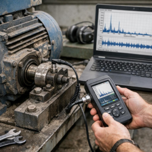
Start by separating electrical noise from real machine behavior. In vibration analysis, a failing bearing may create short, sharp impulses that look “messy” in the time waveform, so aggressive smoothing can hide the exact fault signal your condition monitoring system is supposed to catch.
A practical workflow is to compare the raw signal, FFT spectrum, and trend data before applying any filter. Tools like NI LabVIEW, SKF @ptitude Analyst, or an industrial data acquisition system can help confirm whether the noise is random, speed-related, or coming from a grounding, cabling, or sensor mounting issue.
- Check the installation first: inspect shielded cables, connector tightness, sensor torque, and grounding before changing software settings.
- Use targeted filters: apply band-pass filtering around the expected bearing, gear mesh, or motor frequency instead of broad low-pass filtering.
- Validate with operating context: compare signals at different loads, speeds, and temperatures to avoid filtering out real process-related faults.
For example, on a pump motor, a technician may see high-frequency spikes and assume sensor noise. But if those spikes repeat with bearing defect frequencies in the FFT, filtering them out could delay maintenance and increase repair cost.
One field-tested approach is to save an unfiltered baseline before applying digital filters in your predictive maintenance software. Then use envelope analysis, RMS trending, and spectral comparison together; if a feature appears in multiple views, it is more likely to be a real fault than random sensor noise.
Advanced Noise-Reduction Strategies and Common Setup Mistakes to Avoid
Once grounding and shielding are under control, the next step is to look at signal conditioning and data acquisition settings. In industrial condition monitoring, a good accelerometer can still produce noisy vibration data if the input range, sampling rate, or anti-aliasing filter is poorly configured in platforms like NI LabVIEW, SKF @ptitude, or a PLC-based monitoring system.
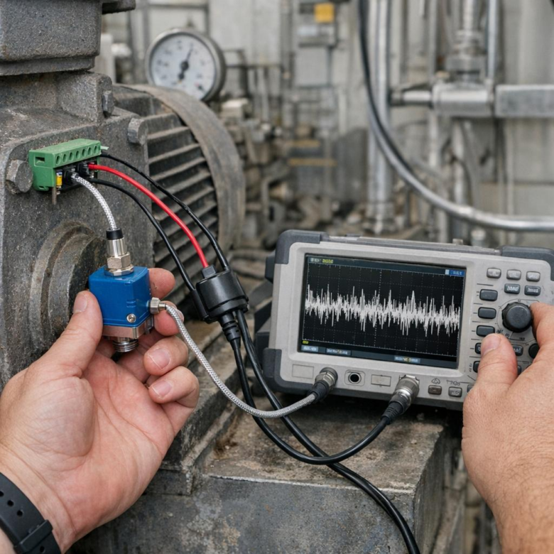
A useful field practice is to compare the raw sensor signal with the processed trend. For example, on a motor-pump skid, I have seen a “bearing fault” disappear after changing the cable route away from a variable frequency drive and enabling the correct low-pass filter in the vibration analyzer. The sensor was fine; the installation was not.
- Use differential inputs: They reject common-mode electrical noise better than single-ended wiring, especially on long cable runs.
- Match filters to the failure mode: Do not over-filter. A bearing defect, cavitation event, or gear mesh issue can be hidden by aggressive smoothing.
- Check sensor power quality: IEPE accelerometers, proximity probes, and pressure sensors need stable excitation; noisy power supplies often look like mechanical faults.
Common setup mistakes include bundling sensor cables with motor leads, using ungrounded junction boxes, mixing shield termination methods, and selecting the wrong sensor sensitivity for the machine speed. These errors increase maintenance cost because teams waste time chasing false alarms instead of real equipment problems.
For difficult cases, use an oscilloscope or portable analyzer such as a Fluke ScopeMeter to inspect the signal before it enters the monitoring software. If the noise exists at the terminal block, software tuning will only hide the issue, not fix it.
Summary of Recommendations
Fixing signal noise is not just a sensor issue-it is a reliability decision. The best results come from treating noise at its source first: installation quality, grounding, shielding, cable routing, and environmental control.
Practical takeaway: avoid compensating for poor signal integrity with excessive filtering. Filtering can help, but it may also hide early fault indicators that condition monitoring systems are designed to detect.
Choose solutions based on risk: simple wiring corrections for minor interference, higher-grade sensors or isolation for persistent noise, and a full system review when false alarms or missed defects affect maintenance decisions.