What breaks first when packet capture scales: the network, the disks, or your assumptions?
At 10, 40, or 100+ Gbps, packet capture stops being a simple logging task and becomes a precision engineering problem where microbursts, buffer overruns, NUMA effects, write amplification, and indexing delays can silently destroy evidence.
Resolving these bottlenecks requires more than faster hardware. It demands an end-to-end design that aligns capture engines, memory paths, storage pipelines, retention policies, and retrieval workflows around the same performance reality.
This article examines where large-scale packet capture and storage systems fail, why conventional fixes often move the bottleneck instead of removing it, and how to build architectures that preserve packets when they matter most.
What Causes Bottlenecks in Large-Scale Packet Capture and Storage Pipelines
Bottlenecks usually appear when packet ingestion speed is higher than what the capture server, storage array, or analysis stack can sustain. In high-throughput environments such as data centers, ISP networks, and financial trading systems, even a small mismatch between network traffic volume and disk write performance can cause packet loss, delayed indexing, or incomplete forensic evidence.
The most common issue I see in real deployments is underestimating storage I/O. For example, a 40Gbps packet capture appliance writing full packets to standard SSDs may work during normal traffic, then fail during a backup window or DDoS investigation because write latency spikes. Tools like Wireshark, tcpdump, Arkime, and enterprise network monitoring platforms are only as reliable as the pipeline feeding them.
- Network interface limits: NICs without proper offloading, RSS, or kernel bypass support can drop packets before they reach the capture application.
- CPU and memory pressure: Deep packet inspection, encryption visibility, and metadata extraction can overwhelm processors during traffic bursts.
- Slow storage architecture: Poor RAID design, low-end NAS devices, or overloaded cloud storage can turn packet capture into a queueing problem.
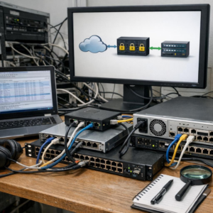
Another hidden cause is poor data retention planning. Keeping every packet for too long increases storage cost, backup complexity, and search latency. A practical approach is to separate hot packet data from archived traffic, use fast NVMe storage for recent captures, and move older files to lower-cost object storage such as Amazon S3 or compatible on-premises platforms.
Configuration matters too. Oversized capture filters, uncompressed PCAP files, and single-threaded processing can waste expensive hardware. The real goal is balance: capture what matters, write it fast, and store it in a format your security operations team can actually query under pressure.
How to Diagnose Throughput, Disk I/O, and Packet Loss Limits in High-Volume Capture Systems
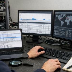
Start by separating the capture path into three checkpoints: network ingress, memory buffering, and storage write performance. On Linux sensors, compare NIC counters from ethtool, interface drops from nload or ifstat, and application-level drops from tools like Zeek, Suricata, or tcpdump. If the NIC shows clean counters but the capture software reports loss, the bottleneck is usually CPU affinity, packet buffer sizing, or disk I/O rather than the switch span port.
- Throughput limit: verify actual Gbps with iperf3, NIC queue stats, RSS configuration, and NUMA alignment.
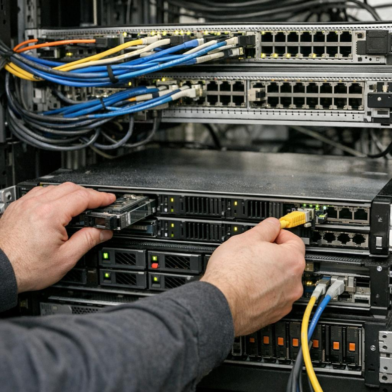
- Disk I/O limit: monitor sustained write latency with iostat, fio, or vendor tools for NVMe storage arrays.
- Packet loss limit: check kernel ring buffers, capture application drops, and packet broker filtering rules.
A common real-world example is a 40Gbps packet capture appliance writing full packets to RAID SSDs during a malware investigation. The dashboard may show “storage healthy,” but iostat can reveal write latency spikes when retention jobs, indexing, and packet capture run at the same time. In that case, reducing packet slice size, moving metadata indexing to another server, or upgrading to enterprise NVMe storage can produce more benefit than buying a larger network tap.
For deeper validation, run a controlled load test before production traffic peaks. Use realistic packet sizes, encrypted traffic patterns, and retention policies, not just synthetic maximum-throughput tests. This gives security teams a reliable view of packet loss risk, storage cost, and whether they need a network packet broker, higher-end capture cards, or managed network monitoring services.
Optimization Strategies for Scalable Packet Retention, Indexing, and Long-Term Storage Performance
Start by separating hot, warm, and cold packet data instead of treating every capture file the same. Keep recent PCAPs on high-speed NVMe storage for fast incident response, move older traffic to lower-cost object storage such as Amazon S3 or on-prem S3-compatible platforms, and define retention policies based on compliance, threat hunting, and legal requirements.
Index only what analysts actually search. Full-payload indexing can crush storage performance and inflate infrastructure cost, so many enterprise network monitoring teams index metadata such as timestamps, IPs, ports, protocols, TLS fingerprints, DNS queries, and flow records while retaining raw packets separately. Tools like Arkime help here because they make large packet repositories searchable without forcing every investigation to scan massive PCAP files directly.
- Use packet slicing for high-volume links when full payload retention is not required.
- Apply compression after capture, not inline, unless hardware acceleration is available.
- Place indexes and packet data on separate disks or storage pools to avoid I/O contention.
In one real-world SOC environment, moving Elasticsearch indexes to dedicated SSD storage while archiving older PCAPs to object storage reduced search delays during malware investigations without removing long-term forensic visibility. The practical lesson is simple: packet capture appliances, SIEM platforms, and storage arrays must be tuned as one pipeline, not as isolated systems.
Also review retention cost monthly. A 40 Gbps network can generate storage bills quickly, so align packet retention with business risk, cybersecurity insurance requirements, and regulatory audit needs rather than keeping everything forever by default.
Final Thoughts on Resolving Bottlenecks in Large-Scale Packet Capture and Storage
Effective packet capture at scale is less about buying faster hardware and more about removing friction across the entire capture path. The right decision depends on where loss, latency, or storage pressure actually appears.
- Measure first: validate drops, write rates, CPU load, and retention needs before redesigning.
- Optimize deliberately: tune capture filters, buffer sizing, disk layout, and indexing around real traffic patterns.
- Scale selectively: add distributed capture, high-speed storage, or specialized appliances only when simpler changes no longer meet requirements.
The best architecture is the one that preserves the packets needed for investigation without overbuilding for traffic that has no operational value.