What if the next electrical fire is already visible-just not to the naked eye?
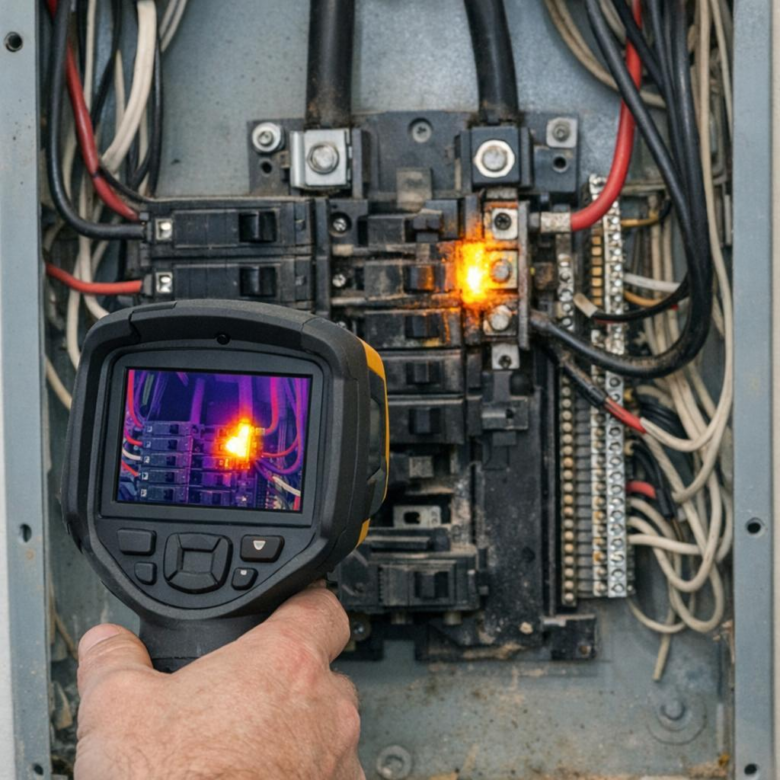
Overheated electrical panels rarely fail without warning; they leave thermal clues in breakers, lugs, busbars, fuses, and conductors long before smoke or shutdown occurs.
Thermal imaging is one of the fastest ways to detect these risks, but only when inspections follow disciplined protocols: correct loading conditions, proper emissivity settings, safe access, comparative analysis, and defensible documentation.
This guide explains the best thermal imaging protocols for identifying overheated electrical panels so maintenance teams can find hidden faults early, prioritize repairs, and reduce fire, downtime, and arc-flash risk.
What Thermal Imaging Reveals About Overheated Electrical Panels
Thermal imaging shows heat patterns that are invisible during a standard electrical panel inspection. An infrared camera can quickly identify overloaded breakers, loose lugs, corroded connections, phase imbalance, failing contactors, and undersized conductors before they turn into downtime, equipment damage, or an arc flash hazard.
In the field, the most useful finding is often temperature difference, not just the hottest spot. For example, if one breaker feeding a rooftop HVAC unit is noticeably hotter than identical breakers under a similar load, that usually points to high resistance, a poor termination, or an overloaded circuit that needs immediate electrical troubleshooting.
- Hot terminals: often linked to loose connections or oxidation.
- Uneven phase temperatures: may indicate load imbalance in commercial electrical systems.
- Warm breakers under normal load: can suggest aging components or poor contact pressure.
Tools such as the FLIR E8-XT or Fluke TiS75+ help technicians capture radiometric images, compare temperatures, and document problem areas for maintenance reports, insurance records, or repair estimates. This documentation is especially valuable for facilities managers who need to justify electrical repair costs or schedule preventive maintenance without shutting down operations unnecessarily.
A good thermographic scan also reveals context. Sun exposure, panel loading, ambient temperature, and recent equipment startup can all affect readings, so images should be taken while the panel is under normal operating load and reviewed by a qualified electrician or certified thermographer.
How to Perform a Reliable Electrical Panel Thermography Inspection
A reliable electrical panel thermography inspection starts before the camera is turned on. The panel should be under normal operating load, ideally at least 40% load, because loose connections and overloaded breakers may not show a meaningful heat signature when equipment is lightly used.
Use a calibrated thermal imaging camera such as FLIR E8-XT or Fluke TiS75+, and set the correct emissivity for painted metal, insulated conductors, or busbar surfaces. In the field, I often see inaccurate reports caused by scanning shiny breaker lugs at the wrong angle, so avoid reflections and compare similar phases or components under the same load.
- Remove panel covers only with proper PPE and qualified electrical safety procedures.
- Capture both thermal and visual images for documentation and insurance reporting.
- Record load conditions, ambient temperature, panel ID, and any corrective action needed.
Scan from top to bottom and compare breakers, terminals, fuses, contactors, neutral bars, and cable terminations. A single hot breaker is not always a defect, but a connection that is significantly hotter than matching components on the same circuit type deserves closer investigation.
For example, in a commercial building inspection, a thermal scan may show one phase lug on a 200-amp panel running noticeably hotter than the others. After shutdown and testing, the maintenance team may find a loose termination or oxidation, which is far cheaper to repair than emergency electrical service after failure.
Finish with a clear electrical thermography report that ranks issues by severity, includes images, and recommends repair, retesting, or load balancing. This makes the inspection useful for facility maintenance, electrical contractor estimates, risk management, and preventive maintenance budgeting.
Common Thermal Imaging Mistakes That Lead to Missed Panel Hot Spots
One of the most common mistakes in electrical panel thermography is scanning under low load. A panel may look normal at 20% capacity, then show a dangerous breaker or lug temperature rise when HVAC, motors, or production equipment are running. For reliable infrared electrical inspection, capture images when the system is operating near its typical peak demand.
Another issue is relying too much on auto temperature scaling. Thermal cameras such as FLIR or Fluke models can make a weak hot spot look dramatic-or hide a serious one-if the span and level are not adjusted manually. Always compare similar phases, breakers, and conductors under similar load instead of judging by color alone.
- Do not scan through closed panel covers unless using approved IR inspection windows.
- Check emissivity settings, especially on shiny copper, aluminum, and plated hardware.
- Record load readings with a clamp meter so the thermal image has real diagnostic value.
A real-world example: in one commercial facility, a technician nearly missed an overheated neutral connection because the panel door was opened for only a few seconds and the image was taken from a poor angle. After allowing a stable view and comparing adjacent terminals, the loose connection was obvious. Small workflow changes can prevent costly electrical repair services, unplanned downtime, and fire risk.
Poor documentation is another expensive mistake. A thermal imaging report should include the infrared image, visual image, load condition, ambient temperature, equipment ID, and recommended corrective action. This makes electrical maintenance decisions easier and supports budgeting for panel upgrades, preventive maintenance contracts, or replacement components.
Summary of Recommendations
Effective thermal imaging is only valuable when it drives action. The best protocol is one that combines consistent scan conditions, qualified interpretation, clear documentation, and timely corrective decisions. Treat abnormal heat patterns as risk indicators, not isolated images, and prioritize findings based on load, temperature rise, component criticality, and safety exposure. For facilities teams, the practical takeaway is simple: standardize inspections, trend results over time, and escalate defects before they become failures. When choosing a protocol or provider, favor electrical expertise, repeatable methods, and reporting that supports maintenance decisions-not just attractive thermal pictures.