Is your pressure loop lying before the process even starts?
Zero-point error in industrial pressure transducers can quietly shift every reading, turning stable control into false alarms, wasted energy, off-spec product, or unsafe operating decisions.
Unlike random noise, zero shift has a fixed bias: the sensor reports pressure when none exists, or misses pressure that is truly present. That makes it especially dangerous in calibration, batching, hydraulic systems, steam networks, and safety-critical monitoring.
This article explains how to identify zero-point error, separate it from span and installation faults, and restore accurate baseline measurement through practical checks, calibration methods, and prevention strategies used in industrial environments.
What Causes Zero-Point Error in Industrial Pressure Transducers?
Zero-point error usually happens when a pressure transducer shows an output signal even when no pressure is applied. In industrial plants, this is often caused by sensor drift, incorrect installation, process vibration, temperature changes, or residual pressure trapped in the impulse line.
One common real-world example is a 4-20 mA pressure transmitter installed on a steam line. If the isolation valve is closed but condensate remains in the sensing line, the technician may assume the sensor has shifted, when the actual issue is trapped pressure creating a false zero reading.
Several practical factors can create or worsen zero offset:
- Mechanical stress: Over-tightened fittings, poor mounting brackets, or pipe strain can slightly deform the sensing diaphragm.
- Temperature effects: High ambient heat near boilers, compressors, or hydraulic power units can shift the sensor baseline.
- Electrical issues: Poor grounding, unstable loop power, moisture in junction boxes, or damaged signal cables can affect the output.
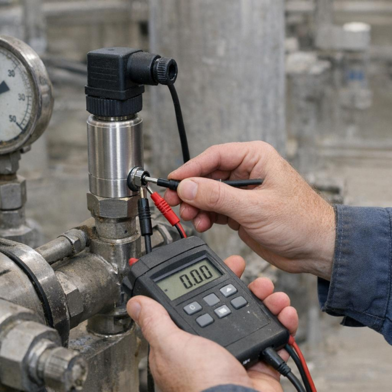
In my experience, many zero errors are not caused by a failed pressure sensor but by installation conditions around it. Before replacing an expensive industrial pressure transducer, technicians should verify the pressure port is vented, check loop power with a multimeter, and confirm readings using a calibrated pressure source such as a Fluke 729 Automatic Pressure Calibrator or a trusted HART communicator.
Harsh service conditions also matter. Chemical exposure, pressure spikes, vacuum cycling, and long-term overload can permanently shift the zero point, making professional pressure calibration services or sensor replacement more cost-effective than repeated field adjustment.
How to Calibrate and Verify Zero Output in Pressure Transducer Systems
Start by isolating the pressure transducer from the process and safely venting it to atmosphere, unless it is an absolute pressure sensor that requires a vacuum reference. Give the device time to stabilize at ambient temperature, because I’ve seen zero drift blamed on the sensor when the real issue was a transmitter powered up cold in a control cabinet.
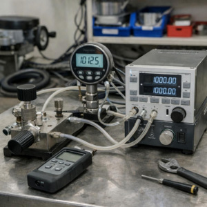
Use a calibrated pressure calibrator or digital manometer, such as the Fluke 719Pro Electric Pressure Calibrator, and verify the output at true zero pressure. For a standard 4-20 mA pressure transmitter, zero pressure should typically read 4.000 mA; for a voltage output transducer, confirm the specified zero signal from the datasheet.
- Check loop power supply voltage before adjusting zero.
- Inspect wiring, shielding, and grounding for signal noise.
- Record “as-found” and “as-left” values for maintenance compliance.
If the zero output is outside tolerance, adjust it through the transmitter’s local trim function, handheld communicator, or PLC/HMI calibration menu. In many industrial pressure measurement systems, especially hydraulic presses or compressed air lines, a small residual pressure trapped in the impulse line can create a false zero error, so crack the fitting carefully and recheck before changing calibration settings.
After adjustment, verify zero again and then apply at least one known pressure point, preferably 50% of span, to confirm the sensor has not developed a span error. This step prevents costly process control issues, unnecessary pressure transducer replacement, and inaccurate maintenance decisions.
Common Zero-Point Drift Mistakes That Reduce Pressure Measurement Accuracy
One common mistake is adjusting the zero while the pressure line is still under residual load. In industrial pressure transducers, even a small trapped pressure in an impulse line can make the technician “correct” a problem that is not actually sensor drift. Always vent or isolate the transmitter properly before performing pressure transmitter calibration.
Another issue is ignoring installation effects. A gauge pressure transducer mounted below the process tap may show an offset because of liquid head pressure, not because the device has failed. I have seen this in water treatment plants where a technician replaced a good sensor, when the real fix was applying the correct elevation compensation during setup.
- Using a low-accuracy test gauge instead of a certified digital pressure calibrator
- Zeroing the device before it reaches operating temperature
- Skipping loop checks after adjustment, especially on 4-20 mA pressure transmitters
Temperature is easy to underestimate. If a pressure sensor is calibrated in a cool maintenance shop and then installed near a hot compressor skid, zero-point drift may return during operation. Let the instrument stabilize in real conditions before making final adjustments.
Relying only on the local display is also risky. Use a calibrated reference device such as a Fluke 754 Documenting Process Calibrator or a HART communicator to verify both the sensor output and control system reading. This helps avoid costly troubleshooting, unnecessary replacement parts, and inaccurate data in PLC, SCADA, or predictive maintenance systems.
Wrapping Up: Resolving Zero-Point Error in Industrial Pressure Transducers Insights
Zero-point error should be treated as an early warning signal, not a minor calibration nuisance. In industrial pressure measurement, the best decision is to verify the cause before adjusting the output.
- Recalibrate when drift is stable and within the sensor’s service limits.
- Inspect installation when mounting stress, impulse line blockage, temperature shift, or vibration is suspected.
- Replace the transducer when zero shift returns repeatedly or exceeds acceptable tolerance.
A disciplined zero-check routine protects process accuracy, reduces false alarms, and prevents unnecessary downtime.