What if your most detailed scale model is wrong by less than a millimeter-but visibly wrong everywhere?
Dimensional inaccuracy is one of the most frustrating failures in high-detail modelmaking because it often hides until parts no longer align, proportions feel “off,” or assemblies drift out of tolerance.
Whether you’re working from CAD files, resin prints, CNC parts, hand-built masters, or mixed materials, small errors can compound through scaling, shrinkage, measurement technique, and finishing processes.
This article explains how to identify the source of dimensional deviation, correct it with practical methods, and build a repeatable workflow that keeps precision intact from reference data to final assembly.
What Causes Dimensional Inaccuracy in High-Detail Scale Models?
Dimensional inaccuracy usually starts before the model is even printed, machined, or cast. In high-detail scale modeling, small errors in CAD files, scale conversion, material shrinkage, and machine calibration can stack up quickly, especially when working with tight tolerances for architectural models, miniatures, product prototypes, or museum replicas.
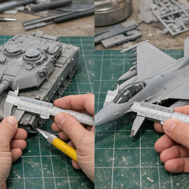
One common issue is relying on visual accuracy instead of measured accuracy. For example, a 1:48 aircraft model may look correct on screen, but if wall thickness, panel gaps, or landing gear dimensions are not checked with digital calipers or tolerance analysis in Autodesk Fusion 360, the final parts may not fit after resin printing.
- Incorrect scaling: Metric-to-imperial conversion errors or rounded scale factors can distort critical dimensions.
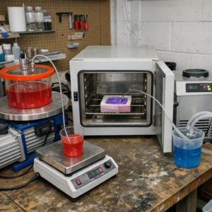
- Material behavior: Resin, plastic, wood, and metal can shrink, warp, or expand depending on curing, temperature, and humidity.
- Machine limitations: A resin 3D printer, CNC router, or laser cutter may need calibration, nozzle compensation, or kerf adjustment.
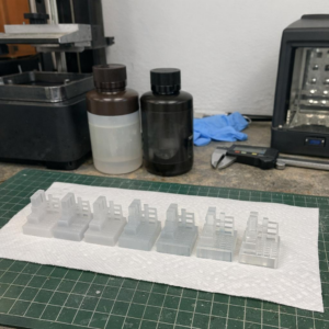
In real production work, I’ve seen highly detailed parts fail simply because the designer ignored post-processing. Sanding, primer, paint layers, and clear coats can add enough thickness to stop doors, panels, or interlocking parts from seating properly. This is why professional model makers often verify key dimensions with digital calipers, test prints, and 3D scanning inspection before committing to full production.
Dimensional accuracy is not just about expensive equipment. It comes from controlled workflow, accurate CAD modeling, reliable measurement tools, and understanding how each material behaves after fabrication.
How to Measure, Compare, and Correct Scale Model Dimensions Accurately
Start with a reliable reference, not guesswork. Use factory drawings, CAD files, museum plans, or verified blueprints, then convert every key dimension using the correct scale ratio before touching the model. For physical checks, a quality digital caliper such as Mitutoyo is worth the cost because small errors in wheelbase, fuselage length, turret diameter, or panel spacing become very visible on high-detail scale models.
Measure in three stages: overall dimensions, major assemblies, then detail parts. For example, on a 1:35 armored vehicle kit, if the real hull is 6,300 mm long, the model should be 180 mm; if your kit measures 176 mm, the error is not “minor” because it affects track fit, suspension alignment, and aftermarket photo-etch parts. I’ve seen builders waste money on resin upgrades when the real issue was an incorrect base kit dimension.
- Compare: Record expected vs. actual measurements in a simple spreadsheet, including tolerance notes.
- Correct: Use styrene shims, sanding blocks, replacement resin parts, or CAD-designed inserts for controlled adjustments.
- Verify: Recheck after primer, since filler and paint can slightly change tight-fitting components.
For advanced corrections, scan the part with a 3D scanner or import reference geometry into Fusion 360 before designing replacement components for resin 3D printing. This is especially useful for aircraft intakes, ship superstructures, custom wheels, and architectural scale models where symmetry matters. If the model is for a client, competition, or product prototype, documenting measurements also protects your time, budget, and final build quality.
Common Calibration, Material, and Assembly Mistakes That Distort Model Accuracy
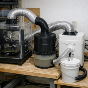
Dimensional errors often start before the first part is printed, cut, or machined. In resin and FDM scale modeling, an uncalibrated printer, incorrect slicer compensation, or worn nozzle can turn a 1:72 aircraft panel line into a visible fit problem. Use PrusaSlicer, Chitubox, or Lychee to check XY compensation, exposure settings, extrusion width, and shrinkage correction before blaming the CAD file.
Material choice is another common source of distortion. Standard PLA may hold detail well, but it can creep under heat; resin can shrink after curing; styrene sheet may warp when solvent cement is over-applied. For example, a resin ship hull that fits perfectly after washing can become slightly bowed after aggressive UV curing, making decks and photo-etched railings misalign.
- Skipping measurement tools: Use digital calipers, preferably a reliable brand like Mitutoyo, to compare printed parts against the scale drawing before assembly.
- Ignoring cure and cooling time: Let resin, cast parts, or 3D printed components stabilize before sanding, drilling, or gluing.
- Forcing assemblies: Tight clamps and fast-setting adhesive can pull thin parts out of square.
Assembly technique matters as much as equipment. Dry-fit major sections, mark reference points, and use a machinist square or small jig when aligning fuselage halves, vehicle chassis rails, or architectural model walls. A small investment in calibration tools and better workflow usually costs less than replacing warped parts, reprinting failed components, or hiring model repair services.
Summary of Recommendations
Dimensional accuracy is ultimately a process choice, not a final correction. The best results come from validating scale, material behavior, machine limits, and measurement methods before detail work becomes irreversible.
For practical decisions, treat every tolerance issue as a trade-off: preserve visual fidelity where the eye matters most, but prioritize fit, alignment, and repeatability where parts must function together. If errors persist, do not simply rescale the model globally-identify whether the cause is design data, fabrication shrinkage, tool calibration, or assembly distortion.
A disciplined test-and-adjust workflow turns high-detail models from fragile showpieces into reliable, buildable scale representations.